
Getting the discharge pipe size wrong is one of the most common and costly mistakes in pump system design. Undersize the pipe and you restrict flow, waste energy, and risk damaging the pump. Oversize it and you end up with slow-moving fluid, sediment build-up, and a system that never quite performs as the pump curve promised. For facilities managers, contractors, and engineers specifying pumping systems across commercial, industrial, and building services applications, understanding how to calculate pump discharge pipe size correctly is a fundamental skill — and one that pays for itself many times over in energy savings and equipment longevity.
This guide walks through the complete calculation process, from flow velocity targets and friction loss to pipe material selection and worked examples. Whether you are sizing pipework for a new installation or troubleshooting an underperforming existing system, the principles here apply across submersible pumps, surface-mounted pumps, sewage pumps, booster systems, and drainage applications.
Why Pump Discharge Pipe Size Matters
The discharge pipe is not a passive component. Its diameter directly determines the velocity of fluid leaving the pump, the friction losses the pump must overcome, and therefore how far the pump operates from its best efficiency point (BEP). A pipe that is even one nominal size too small can push the operating point well to the left of the BEP, increasing power consumption, generating heat, and accelerating wear on seals and bearings.
The relationship between pipe diameter, velocity, and friction loss is exponential, not linear. Halving the pipe diameter increases velocity fourfold at the same flow rate. Because friction loss is proportional to the square of velocity (from the Darcy-Weisbach equation), that doubling of velocity produces four times the friction loss. This is why small errors in pipe sizing have disproportionate consequences.
⚠️ Important: Discharge pipe sizing affects more than just flow rate. Poorly sized pipework puts mechanical stress on the pump casing, increases noise and vibration, and shortens pump life. Always size the pipe for the system, not just to match the pump flange.
Target Velocity: The Starting Point for Any Calculation
Before calculating pipe diameter, you need a target fluid velocity. Velocity is the single most practical starting point because it ties directly to friction loss, erosion risk, and system noise. For most pumping applications involving water or clean liquids, UK engineering practice and guidance from sources including BS EN 806 and CIBSE Guide C recommend the following velocity ranges for discharge pipework:
| Application | Recommended discharge velocity (m/s) | Notes |
|---|---|---|
| General industrial / commercial | 1.5 – 3.0 | Most common range for water and clean liquids |
| Sewage and solids-handling | 0.9 – 2.5 | Minimum 0.9 m/s to prevent solids settling |
| Building services (cold water) | 1.0 – 2.0 | BS EN 806-3 maximum 2.0 m/s continuous flow |
| Long pipe runs (>100 m) | 1.0 – 1.5 | Lower velocity minimises friction losses on extended runs |
| Short connections (<10 m) | Up to 3.0 | Higher velocity acceptable where friction losses are minimal |
Velocities above 3.0 m/s in standard pipework cause turbulence, noise, erosion of pipe walls and fittings, and water hammer risk on pump stop. Velocities below 0.9 m/s in sewage or slurry applications allow solids to settle and block the pipe. For clean water systems, velocities below 0.5 m/s can lead to stagnation and air pockets at high points.
Suction vs Discharge Velocity Targets
Discharge pipework is typically sized for a higher velocity than suction pipework. On the suction side, velocity should be kept below 1.5 – 2.0 m/s to protect NPSH (Net Positive Suction Head) margins and prevent cavitation. On the discharge side, you have more headroom, but the practical upper limit in most commercial and industrial settings is 3.0 m/s for continuous operation.
The Core Calculation: Pipe Diameter from Flow Rate and Velocity
Once you have a target velocity, calculating the required pipe internal diameter is straightforward. The formula comes from the continuity equation for incompressible flow:
Q = A × v
Where Q is flow rate (m³/s), A is the pipe cross-sectional area (m²), and v is the fluid velocity (m/s). Since A = π × (d/2)², this rearranges to:
d = √(4Q / π × v)
In practice, it is more useful to work in litres per minute and millimetres. The equivalent formula becomes:
d (mm) = √(21,220 × Q(L/min) / v(m/s))
Worked Example: Sizing a Discharge Pipe for a Sewage Pump
A submersible sewage pump delivers 240 litres per minute. The discharge run is 45 metres to a rising main. Solids must be kept in suspension, so the minimum acceptable velocity is 0.9 m/s and the target is 1.5 m/s.
Using the formula at 1.5 m/s:
d = √(21,220 × 240 / 1.5) = √(3,395,200) = 58.3 mm minimum internal diameter
The next standard nominal bore above 58.3 mm is 65 mm NB (DN65). Checking the pipe manufacturer’s bore table confirms the internal diameter of a typical DN65 PVC pipe is 70.6 mm, giving an actual velocity of:
v = (240/60) / (π × 0.0353²) = 4 L/s / 0.00391 m² = 1.02 m/s
This is above the 0.9 m/s minimum for solids suspension and within the acceptable range. DN65 is the correct choice for this application.
💡 Pro tip: Always calculate using the pipe’s actual internal bore, not the nominal size. For PVC, HDPE, and steel pipes, the internal diameter varies by pressure rating and schedule. Using nominal size alone will undersize the pipe.
Friction Loss: How Pipe Length and Fittings Add to System Head
The velocity calculation tells you the minimum pipe diameter. The next step is to quantify the friction losses that diameter will generate over your actual pipe run. These losses add directly to the total head the pump must deliver, which affects pump selection and energy consumption.
Friction loss in straight pipe is calculated using the Darcy-Weisbach equation:
h_f = f × (L/d) × (v²/2g)
Where h_f is head loss in metres, f is the Darcy friction factor (typically 0.015 – 0.025 for turbulent flow in commercial pipework), L is pipe length in metres, d is internal diameter in metres, v is velocity in m/s, and g is gravitational acceleration (9.81 m/s²).
For practical purposes, most engineers use pre-calculated friction loss tables rather than solving this equation from scratch. The key figures to know:
| Nominal pipe size | Flow rate (L/min) | Velocity (m/s) | Approx friction loss (m per 100 m of pipe) |
|---|---|---|---|
| 50 mm | 100 | 1.41 | 4.2 m |
| 65 mm | 200 | 1.50 | 3.8 m |
| 80 mm | 300 | 1.46 | 3.2 m |
| 100 mm | 500 | 1.50 | 2.5 m |
| 150 mm | 1,100 | 1.49 | 1.6 m |
Values are approximate for clean water at 15°C in smooth PVC or HDPE pipe. Actual losses vary with pipe roughness, fluid temperature, and Reynolds number.
Adding Losses for Fittings and Valves
Fittings — bends, tees, reducers, non-return valves, gate valves — all add resistance. The standard method for commercial pipework is to express each fitting as an equivalent pipe length (in metres), then add that to the straight pipe run before calculating total friction loss.
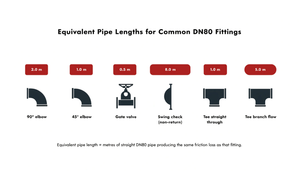
Commonly used equivalent lengths for standard fittings at DN80:
- 90° elbow (standard): 2.0 m equivalent pipe length
- 45° elbow: 1.0 m equivalent pipe length
- Gate valve (full bore, fully open): 0.5 m equivalent pipe length
- Non-return valve (swing check): 8.0 m equivalent pipe length
- Tee (straight through): 1.0 m equivalent pipe length
- Tee (branch flow): 5.0 m equivalent pipe length
Non-return valves are frequently underestimated. A single swing check valve in a DN80 system adds the equivalent of 8 metres of pipe friction. In a 20-metre pipe run, that is a 40% increase in effective length, and therefore a 40% increase in friction loss from that section. Specifying a low-resistance non-return valve, or a ball-type check valve, can reduce this significantly.
Worked Friction Loss Calculation: Full System Example
A surface-mounted surface pump is delivering 300 litres per minute through an 80 mm discharge pipe. The pipe run is 35 metres to a storage tank 8 metres above the pump. The system includes two 90° elbows, one gate valve, and one swing check valve.
Step 1: Equivalent pipe length for fittings
Two 90° elbows: 2 × 2.0 m = 4.0 m
Gate valve: 0.5 m
Swing check valve: 8.0 m
Total equivalent length for fittings: 12.5 m
Step 2: Total effective pipe length
35 m (straight run) + 12.5 m (fittings) = 47.5 m total effective length
Step 3: Friction loss from table
At 300 L/min through DN80, friction loss is approximately 3.2 m per 100 m. Over 47.5 m: (47.5 / 100) × 3.2 = 1.52 m friction head
Step 4: Total system head
Static head (vertical lift): 8.0 m
Friction head: 1.52 m
Total dynamic head (TDH): 9.52 m
This TDH figure is what you use to select the pump from the manufacturer’s curve. Always add a safety margin of 10 – 15% to account for pipe ageing, minor installation deviations, and future increases in demand. In this case: 9.52 × 1.1 = 10.5 m TDH minimum pump specification.
Pipe Material and Its Effect on Sizing
The internal roughness of the pipe material affects friction losses. Smooth pipes produce less friction at the same velocity. This matters when comparing different pipe materials for the same application, and when specifying whether to upsize or whether the calculated size is adequate.
| Pipe material | Roughness coefficient (k, mm) | Typical applications | UK standard |
|---|---|---|---|
| PVC / uPVC | 0.0015 | Drainage, sewage, irrigation | BS EN 1401, BS EN 13476 |
| HDPE | 0.003 | Water supply, chemical transfer | BS EN 12201 |
| Stainless steel (304/316) | 0.002 | Food processing, clean water, marine | BS EN 10217-7 |
| Galvanised steel | 0.15 | General industrial, heating systems | BS EN 10255 |
| Cast iron | 0.26 | Legacy systems, water mains | BS EN 545 |
In practice, the difference between PVC and stainless steel is small enough that it does not usually change the pipe size selection. Where it becomes significant is in older galvanised or cast iron systems, where roughness can be substantially higher due to internal corrosion, scaling, or deposit build-up. When assessing an existing system, always apply a condition factor to account for pipe age.
Should You Upsize from the Pump Discharge Flange?
A common question when designing discharge pipework is whether to match the pipe diameter to the pump’s discharge flange or to upsize. The general guidance from pump engineering practice is:
- For short connections (under 10 m), matching the flange size is usually acceptable provided the velocity stays within the recommended range.
- For longer runs (over 20 m), upsizing by one nominal bore is often cost-effective. The reduction in friction loss reduces the head the pump must generate, which lowers energy consumption over the life of the system.
- For very long runs (over 100 m), a full hydraulic analysis comparing pipe capital cost against pump energy cost over the system’s design life is worthwhile before specifying pipe size.
When upsizing, fit a concentric reducer at the pump discharge flange to transition smoothly. Avoid abrupt changes in diameter close to the pump, as these create turbulence and can contribute to cavitation on the discharge side.
⚠️ Important: Never undersize the discharge pipe to create backpressure as a substitute for a control valve. Sustained high-velocity flow in an undersized pipe will erode fittings, increase noise, and lead to premature pump failure.
Application-Specific Sizing Considerations
Sewage and Solids-Handling Pumps
Sewage pump discharge pipework has a minimum velocity constraint that clean-water systems do not: the self-cleaning velocity. For pumped sewage containing solids, the minimum flow velocity to keep solids in suspension is 0.9 m/s. Sizing below this velocity in any section of the discharge run — including horizontal sections and rising mains — risks solid accumulation and blockages.
For sewage applications, the practical design approach is to size for a minimum of 1.0 m/s throughout, with the target velocity at 1.2 – 1.5 m/s for normal operating conditions. This provides a margin above the self-cleaning threshold even at reduced flow rates (such as when only one pump of a duplex system is running).
Sump Pumps and Drainage Pumps
Sump pump discharge typically uses smaller bore pipework than sewage systems, as the fluids involved are usually clean or lightly contaminated water without large solids. Standard guidance for residential and light commercial sump applications recommends a minimum 32 mm internal bore, with 40 – 50 mm preferred for runs exceeding 15 metres. For commercial or industrial applications with higher flow rates, apply the standard velocity calculation.
A common installation error with sump pumps is fitting a discharge pipe that is the same diameter as the pump outlet socket but then reducing it immediately to a smaller bore to pass through a wall or floor. This creates a constriction that the pump curve was never designed to handle and results in reduced flow, overheating, and shortened pump life.
Booster Pumps and Pressurised Systems
Discharge pipe sizing for booster pump systems follows the same velocity principles, but the higher operating pressures involved make pressure rating of fittings and pipe material a parallel consideration. Specifying a pipe diameter without specifying the correct pressure class for the application is a common oversight, particularly on systems operating above 6 bar. Always verify that the selected pipe and fittings are rated for the pump’s maximum shut-off pressure, not just the normal operating pressure.
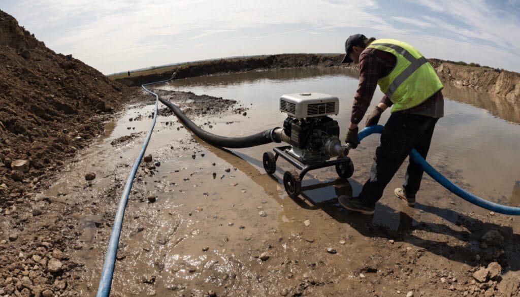
Engine-Driven and Surface Pumps for High-Volume Applications
For engine-driven pumps used in dewatering, irrigation, or emergency pumping, discharge pipework is often temporary — layflat hose or aluminium pipe rather than permanent installed pipework. The same velocity principles apply, but the practical constraints are different. Layflat hose introduces higher friction coefficients than rigid pipe, and any kinks or restrictions in hose routing add significant resistance. On temporary installations, running the hose in the shortest practical straight route and avoiding tight bends will often achieve more improvement in performance than upsizing the hose diameter.
Recommended Pump Pipework and Accessories from AES Rewinds
Correctly sizing discharge pipework requires correctly sized pumps and compatible accessories. At AES Rewinds, we stock a comprehensive range of pumps for industrial, commercial, and drainage applications.
Browse our full pump range:
- Sewage pumps — submersible and grinder pumps for sewage and wastewater applications
- Sump and drainage pumps — for basement, flood, and industrial drainage
- Surface-mounted pumps — for transfer, irrigation, and general pumping
- Booster pumps — for pressure boosting in building services and commercial systems
- Hose and accessories — discharge hose, fittings, and connections for temporary and permanent installations
Our team can help you select the right pump and verify that your discharge pipework specification will give the performance your system demands. Contact us for advice on any application.
Frequently Asked Questions
What is the correct velocity for pump discharge pipework?
For most commercial and industrial applications handling clean water or lightly contaminated liquids, the target velocity range is 1.5 – 3.0 m/s. For sewage and solids-handling applications, a minimum of 0.9 m/s is required to prevent solids settling, with 1.2 – 1.5 m/s as the practical design target. Velocities above 3.0 m/s in standard pipework are generally avoided due to noise, erosion, and water hammer risk.
Should the discharge pipe be the same size as the pump flange?
Not necessarily. The pump discharge flange size is determined by the pump manufacturer for connection purposes, not as a recommendation for the connected pipework. For long runs, upsizing the discharge pipe by one nominal bore is often cost-effective. For short connections, matching the flange size is usually acceptable provided the resulting velocity falls within the recommended range.
How do I calculate total dynamic head for pump selection?
Total dynamic head (TDH) is the sum of static head (the vertical lift from pump to discharge point), friction losses in the discharge pipe (including equivalent lengths for fittings), and any pressure at the discharge point above atmospheric. The sump pump sizing guide covers TDH calculation in detail for drainage applications.
What is the minimum pipe size for a sewage pump?
The minimum pipe bore for sewage applications depends on the solid particle size the pump is rated to handle. A pump rated for 50 mm free passage requires a minimum 50 mm internal bore throughout the discharge system — including at reducers, bends, and any rising main connections. Constricting the discharge below the pump’s rated passage diameter defeats the purpose of the solids-handling impeller and causes blockages.
How much head does a non-return valve add to the system?
A standard swing check valve adds approximately 8 – 12 metres of equivalent pipe length depending on size and type, which translates to significant friction head in smaller bore systems. Low-resistance check valves (ball type or guided disc) can reduce this to 2 – 4 metres equivalent length. Where energy efficiency is a priority and multiple check valves are required, specifying low-resistance types is worthwhile.
Does pipe length affect which pump I need?
Yes. Every additional metre of pipe adds friction head to the system. For a DN80 pipe at 300 L/min, each additional 100 metres of effective pipe length adds approximately 3.2 metres of head. On long runs, this can require a significantly larger pump than the static head alone would suggest. Always calculate total friction losses before finalising pump selection — and revisit the calculation if the pipe route changes during installation.
Can I use the same pipe size for both suction and discharge?
It is common to upsize the suction pipe relative to the discharge pipe rather than match them. Suction pipework should typically be sized for a lower velocity (0.5 – 1.5 m/s) to protect NPSH margins and prevent cavitation. If the discharge pipe is correctly sized at 1.5 – 2.0 m/s, using the same size for the suction side is often adequate for short suction runs, but upsizing by one bore is good practice for any suction run exceeding 5 metres.
What happens if the discharge pipe is too small?
An undersized discharge pipe drives the pump to operate to the left of its best efficiency point. This increases power consumption, generates heat in the pump casing and motor, accelerates seal wear, and — in severe cases — can trigger automatic thermal protection cutouts. The pump may also develop excessive noise and vibration. If an existing system is underperforming, checking whether the discharge pipe is correctly sized is one of the first diagnostic steps worth taking.
Key Takeaways
- Target a discharge velocity of 1.5 – 3.0 m/s for most commercial and industrial applications. For sewage systems, maintain a minimum 0.9 m/s throughout to prevent solids settling.
- Calculate minimum internal pipe diameter using d (mm) = √(21,220 × Q(L/min) / v(m/s)), then round up to the next standard nominal bore.
- Always use the pipe’s actual internal bore from manufacturer bore tables, not the nominal size, when verifying velocity and friction loss.
- Non-return valves contribute significantly to friction head. A standard swing check valve in a DN80 system adds approximately 8 metres of equivalent pipe length.
- For pipe runs over 20 metres, compare the cost of upsizing by one nominal bore against the long-term energy saving from reduced friction losses. The payback period is often under five years.
- Total dynamic head (TDH) for pump selection must include both static head and all friction losses. Add a 10 – 15% safety margin before specifying the pump.
Related Articles
- What Size Sump Pump Do I Need? Complete Guide — detailed TDH calculations and sizing for basement drainage applications.
- How to Choose a Sewage Pump — pump type selection, flow rate calculation, and UK Building Regulations guidance.
- How Does a Sewage Grinder Pump Work — covers grinder pump design and pipework requirements for pressurised sewage systems.
- What Is a Booster Pump and When Do You Need One? — including pressure calculations and compliance with UK Water Regulations 1999.