
If you are specifying a surface-mounted pump, one of the most consequential decisions you will make is how far above the water source the pump sits. Get this wrong and the pump will either fail to prime, run in a state of continuous cavitation, or burn out within months. Pump suction lift and Net Positive Suction Head (NPSH) are the two interconnected concepts that govern this decision, yet they are frequently misunderstood, misquoted, or simply ignored until a pump fails on site.
This guide is written for facilities managers, contractors, and engineers who need to specify, install, or troubleshoot surface-mounted pumps in commercial and industrial settings. It covers what pump suction lift actually is, how NPSHa and NPSHr work in practice, how to carry out a worked calculation in metric units, and what to do when your installation pushes against the physical limits of suction lift.
What Is Pump Suction Lift?
Pump suction lift is the vertical distance between the surface of the liquid being pumped and the centreline of the pump impeller, where the pump is positioned above the liquid source. In this configuration, the pump does not draw liquid upward in any active sense. What actually happens is that atmospheric pressure pushes the liquid up the suction pipe as the pump creates a low-pressure zone at its inlet.
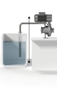
This has an immediate practical implication: the pump is limited by atmospheric pressure, not by its own power output. At sea level, standard atmospheric pressure supports a water column of approximately 10.33 metres. That is the theoretical ceiling for suction lift. In practice, friction losses in the suction pipe, vapour pressure of the liquid, and the pump’s own NPSH requirements reduce the usable limit to around 7 to 8 metres for clean cold water at low altitude.
Why Submersible Pumps Avoid This Problem Entirely
A submersible pump sits below the liquid surface and pushes water upward under positive pressure. It has no suction lift requirement because the pump inlet is always flooded. If your installation allows for it, submerged operation removes suction lift from the equation entirely and is the more reliable choice for high-lift or high-temperature applications. For applications where surface mounting is required, such as engine-driven dewatering pumps or self-priming trash pumps, understanding suction lift becomes non-negotiable.
Understanding NPSH: The Two Numbers You Need
NPSH is measured in metres of head rather than pressure (bar or Pa) because head is fluid-independent. A pump will lift fluid to the same head regardless of the fluid’s density, which makes head the consistent basis for comparing pump performance across different applications.
There are two values to understand: the one the system provides (NPSHa) and the one the pump requires (NPSHr).
NPSHa: What the System Can Deliver
NPSHa (Net Positive Suction Head Available) is a property of your installation. It describes the pressure available at the pump inlet, expressed as a head, above the vapour pressure of the liquid. You calculate it from your system geometry, pipe losses, altitude, and liquid temperature.
NPSHr: What the Pump Demands
NPSHr (Net Positive Suction Head Required) is a property of the pump, published by the manufacturer from controlled test data. It is defined as the inlet pressure at which the pump’s discharge head drops by 3% due to the onset of cavitation. This is why you may see it written as NPSH3 in datasheets.
The fundamental rule is straightforward:
NPSHa must always exceed NPSHr — with a safety margin of at least 0.5 to 1 metre.
If NPSHa falls below NPSHr, the liquid at the pump inlet will begin to vaporise. Vapour bubbles form, travel through the impeller, then collapse violently as pressure rises on the discharge side. This is cavitation: a process that causes noise, vibration, impeller erosion, and ultimately pump failure.
How to Calculate NPSHa
The formula for NPSHa in metres, used for an open-surface liquid source at atmospheric pressure, is:
NPSHa = (Patm − Pvap) ÷ (ρ × g) − Hs − hf − e
| Variable | Description | Typical value (cold water at sea level) |
|---|---|---|
| Patm | Atmospheric pressure (Pa) | 101,325 Pa |
| Pvap | Vapour pressure of liquid (Pa) | 2,338 Pa (water at 20°C) |
| ρ | Liquid density (kg/m³) | 998 kg/m³ (water at 20°C) |
| g | Acceleration due to gravity (m/s²) | 9.81 m/s² |
| Hs | Static suction lift (m) | Measured on site |
| hf | Friction losses in suction pipe (m) | Calculated from pipe data |
| e | Safety margin (m) | Minimum 1 m recommended |
For clean cold water at sea level, before friction losses and safety margins:
(101,325 − 2,338) ÷ (998 × 9.81) = 10.11 m
That is your starting budget. Every metre of suction lift, every metre of friction loss, and every safety margin deduction comes off this figure.
Worked Example
A contractor is installing a self-priming surface pump to dewater a tank. The pump sits 4 metres above the water surface. The suction pipe is 50mm bore, 6 metres long, with two 90° elbows (equivalent pipe length 8 metres total including fittings). Friction loss for this pipe is calculated at approximately 0.8 m. The liquid is clean water at 20°C, the site is at sea level.
- Starting pressure head: 10.11 m
- Less suction lift (4 m): 10.11 − 4.00 = 6.11 m
- Less friction losses (0.8 m): 6.11 − 0.80 = 5.31 m
- Less safety margin (1 m): 5.31 − 1.00 = 4.31 m NPSHa
The pump selected must have an NPSHr of 4.31 m or less at the intended flow rate.
⚠️ Important: NPSHr is not constant. It increases as flow rate rises. Always check the NPSHr at your actual operating point on the pump curve, not just at BEP (Best Efficiency Point).
NPSHa Calculator
Use this calculator to find your available NPSH for a suction lift application using clean water at sea level.
Affects vapour pressure. Warm water significantly reduces NPSHa.
Vertical distance from water surface to pump impeller centreline.
Include losses from pipe length, elbows, valves, and strainers.
Minimum 0.5 m recommended. Use 1.0 m for general commercial applications.
for complex applications involving hot liquids, elevated sites, or non-water fluids, consult the pump manufacturer's technical team.
Factors That Reduce Available NPSHa
Understanding the calculation is one thing. Knowing what erodes your NPSHa margin in real installations is what keeps pumps running.
Altitude Above Sea Level
Atmospheric pressure falls as altitude rises. For every 300 metres of elevation, you lose roughly 0.3 to 0.35 metres of NPSHa. At an altitude of 500 metres (common in parts of Wales, the Pennines, and the Scottish Highlands), you lose approximately 0.6 metres from your starting budget. For most UK commercial applications this is minor, but it should not be forgotten on highland or upland sites.
Liquid Temperature
Warmer liquids have higher vapour pressures. As vapour pressure rises, the atmospheric head available to push liquid into the pump falls. Pumping hot water or heated process liquids at surface level requires careful recalculation. Water at 80°C has a vapour pressure of approximately 47,400 Pa, which removes around 4.8 metres from your available head before lift or friction losses are considered.
Suction Pipe Friction Losses
Every metre of pipe, every elbow, valve, strainer, and foot valve adds resistance on the suction side. These losses are particularly damaging because they occur on the low-pressure side of the pump, directly reducing NPSHa. For this reason, understanding how to calculate pump head and flow rate is essential before finalising suction pipework design.
Key rules for suction pipework:
- Keep the suction pipe as short and straight as possible.
- Size the suction pipe one diameter larger than the pump inlet where practical.
- Avoid any high points in the suction line where air can collect.
- Use eccentric reducers at the pump inlet, installed with the flat side uppermost, to prevent air pockets forming at the top of the pipe.
- Install foot valves at the bottom of the suction pipe to maintain prime between pump cycles.
⚠️ Important: A concentric reducer on a suction line creates an air trap at the top of the taper. This is one of the most common causes of loss of prime on otherwise correctly specified systems. Always use eccentric reducers on the suction side.
Choosing the Right Pump for High Suction Lift Applications
Not all pump types handle suction lift equally. When your application requires significant lift above the source, pump selection becomes as important as the NPSHa calculation.
Self-Priming Centrifugal Pumps
Self-priming surface-mounted pumps are designed to evacuate air from the suction line and prime themselves without external assistance. Our guide to how self-priming pumps work covers the mechanics in detail. Most self-priming centrifugal pumps are rated for suction lifts of 5 to 7 metres under normal operating conditions. Above 7 metres, reliability drops sharply and cavitation risk increases.
Engine-Driven Pumps
Engine-driven pumps used for site dewatering and emergency drainage often operate in suction lift conditions, drawing from sumps, tanks, or flooded excavations. Petrol and diesel units fitted with self-priming pump ends can typically achieve 6 to 8 metres of suction lift. Manufacturer datasheets should always be checked, as suction lift performance varies significantly between pump ends and impeller designs.
Submersible Pumps: The Suction-Free Alternative
Where suction lift is consistently close to the practical limit, a submersible pump is almost always the better technical choice. With no suction lift requirement, drainage and dewatering submersible pumps eliminate the risk of cavitation from suction conditions entirely. For borehole and deep well applications, as our borehole pump selection guide explains, the submersible principle is the only practical solution at any meaningful depth.
Common Mistakes That Lead to Pump Failure
Most cavitation and priming failures traced back to suction conditions come from the same handful of errors. Understanding them is more useful than any checklist.
Using the Pump's Rated Maximum Suction Lift as a Target
Manufacturers quote maximum suction lift under ideal conditions: short straight pipe, cold clean water, sea level. In practice, friction losses, temperature, altitude, and safety margins mean the real usable lift is always lower. Treat the rated maximum as a ceiling, not a design target.
Ignoring NPSHr at Operating Flow Rate
NPSHr is not constant. On a typical centrifugal pump curve, NPSHr rises steeply as flow increases beyond BEP. A pump specified at a moderate flow rate may have an NPSHr of 2 m, but at its maximum flow it may require 5 m or more. Always check the pump curve at your actual operating point. Our A-Z pump terminology guide explains BEP and pump curves in accessible terms.
Installing a Foot Valve That Is Too Small
A foot valve sized to match the suction pipe diameter rather than to minimise pressure drop will create significant friction loss at low cost. Always size the foot valve for minimum velocity and check the manufacturer's pressure drop data.
Air Leaks in Suction Pipework
Any leak in the suction line allows air to enter. Because the suction side is under negative pressure, even a small gap around a gasket or a loose union will introduce air continuously. This causes intermittent loss of prime and can mimic cavitation. Suction pipework should be assembled and pressure-tested before commissioning.
Recommended Pumps from AES Rewinds
Choosing the right pump for a suction lift application starts with an accurate NPSHa calculation, but it ends with a pump whose NPSHr and self-priming capability match your site conditions.
At AES Rewinds, we stock a comprehensive range of surface-mounted and engine-driven pumps suited to suction lift applications, including self-priming centrifugal units, trash pumps, and high-head surface pumps for commercial and industrial use.
Browse our range:
- Surface-mounted pumps — including self-priming centrifugal and high-head units
- Engine-driven pumps — for site dewatering and remote applications
- Drainage and dewatering pumps — where a submersible solution removes the suction lift constraint
Our team can help you verify your NPSHa figures and match the right pump to your application. Contact us for technical advice on suction lift specifications.
Frequently Asked Questions
What is the maximum pump suction lift for water in the UK?
The theoretical maximum pump suction lift for cold water at sea level is approximately 10.33 metres, determined by atmospheric pressure. In practice, accounting for friction losses, vapour pressure, and a recommended safety margin, the usable maximum for most commercial applications is 7 to 8 metres. Sites at higher altitude or pumping warm water will have a lower practical limit.
What happens if NPSHa is less than NPSHr?
If your available NPSH falls below the pump's required NPSH, the liquid at the pump inlet will begin to vaporise. Vapour bubbles form and then collapse violently as they pass through the impeller, a process called cavitation. This causes noise, vibration, erosion of the impeller, and accelerated pump failure. Understanding pump head and flow rate helps contextualise where suction conditions fit into the broader system design.
How do I reduce NPSHr if my NPSHa margin is tight?
NPSHr is a fixed property of the pump at a given speed and flow. You cannot reduce it by system design. Your options are: select a different pump with a lower published NPSHr; reduce your required flow rate (NPSHr falls at lower flow on most centrifugal pumps); lower the pump closer to the liquid surface to reduce suction lift; or switch to a submersible pump that eliminates the suction lift condition entirely.
Does liquid temperature affect suction lift?
Yes, significantly. As water temperature rises, vapour pressure increases and atmospheric head available to push liquid into the pump decreases. Water at 60°C has a vapour pressure roughly ten times higher than water at 20°C, reducing available suction head by around 2 metres. Hot liquid applications almost always require the pump to be positioned at or below the liquid level.
What is an eccentric reducer and why does suction pipework need one?
An eccentric reducer connects two different pipe diameters on the suction side of a pump. Unlike a standard concentric reducer (symmetrical on both sides), an eccentric reducer has one flat side. Installed with the flat side uppermost, it allows liquid to flow through without creating an air pocket at the top of the taper. Air pockets on the suction side cause loss of prime and cavitation-like symptoms. See the self-priming pump guide for more on maintaining prime in surface installations.
Can I use a sump pump in a suction lift application?
No. A sump pump is a submersible unit designed to sit in or near the liquid it pumps. It has no suction lift capability and requires a flooded inlet to operate. For above-source pumping, a self-priming surface pump or engine-driven pump is the correct product type.
What is NPSH3 on a pump datasheet?
NPSH3 (sometimes written NPSHr or NPSH3%) is the manufacturer's published Net Positive Suction Head Required figure, defined as the inlet pressure at which the pump's discharge head drops by 3% due to the onset of cavitation. It is determined through standardised testing with water at 20°C. For all operating calculations, your NPSHa must exceed this figure by a minimum safety margin of 0.5 to 1 metre.
Key Takeaways
- Pump suction lift is limited by atmospheric pressure, not pump power. The theoretical ceiling is 10.33 m; the practical usable maximum for clean cold water is 7 to 8 m.
- NPSHa is a system property you calculate. NPSHr is a pump property published by the manufacturer. NPSHa must always exceed NPSHr by at least 0.5 to 1 metre.
- Temperature, altitude, and suction pipe friction all reduce NPSHa. Calculate with real site conditions, not idealised figures.
- Always check NPSHr at your actual operating flow rate, not just at BEP. NPSHr rises sharply at high flow.
- Eccentric reducers, large-bore suction piping, and minimal pipe runs are the key design choices that protect your NPSHa margin.
- Where suction lift is consistently near the practical limit, a submersible pump is the more reliable long-term solution.
Related Articles
- Understanding Pump Head and Flow Rate — how to calculate total dynamic head for the full system, suction side included
- Self-Priming Pumps: How They Work and Their Applications — in-depth guide to self-priming mechanics and suction line requirements
- How to Select the Right Well and Borehole Pump — why submersible borehole pumps bypass suction lift constraints entirely
- A-Z of Pump Terminology — definitions of BEP, TDH, NPSH, cavitation, and all key specification terms
- Sewage Pump vs Sump Pump — comparison guide for selecting the right submersible pump type